Note: This project was completed with a team of 6 people. While the group work was highly cooperative, my primary contributions dealt with thermocouple temperature validation and internal temperature calculations, as well as the circuitry/wiring, and team organization. I want to give credit to my team members: Jacky Chen, Olesya Kondrateva, Luke Santosham, Yasna Vafi, and Ethan Wong.
Overview
This project was developed for my ELEC 291 course at UBC. The objective was to engineer a Reflow Oven Controller, converting a standard 1500W toaster oven into a precision tool capable of following specific temperature profiles to properly mount SMD components onto PCBs. To meet strict timing and memory constraints, the firmware was written entirely in bare-metal 8051 assembly language and executed on an 8052 soft-processor running on a DE10-Lite FPGA.
The system features:
- Accurate Temperature Tracking measuring between 25°C and 240°C with an accuracy of +/- 3°C relative to a calibrated multimeter.
- Staged Profile Execution accurately navigating the four standard stages of SMD reflow: preheat, soak, reflow, and cooling.
- Automated Safety Mechanisms including a system abort if the oven fails to reach 50°C within 60 seconds, preventing thermal runaway.
- Live User Feedback via an LCD, real-time Python serial telemetry, and audible beep codes for state transitions and errors.
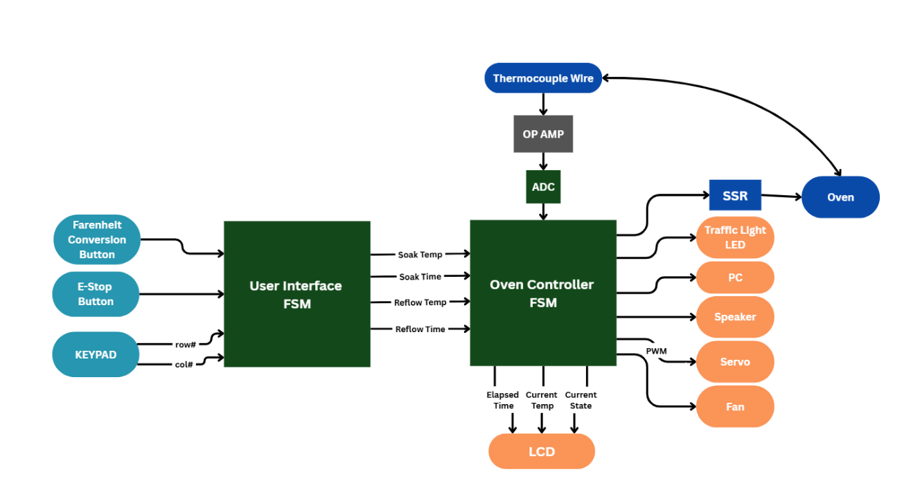
System Flow
- Sensors continuously read the oven’s ambient heat via a K-type thermocouple and custom Op-Amp circuit.
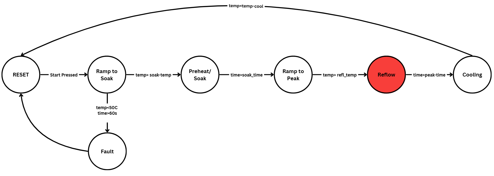
- 8051 FSM (Finite State Machine) evaluates the elapsed time and current temperature to determine the active operational state (
RAMP_TO_SOAK,SOAK,REFLOW,COOLING). - Power Control Logic utilizes an on-off control strategy, selectively driving an SSR to maintain heat curves while compensating for the oven’s thermal inertia.
- Python Dashboard receives real-time diagnostic data over UART, plotting the heating curve against threshold targets.
Building this complex hardware-software integration required highly organized collaboration within our six-person engineering team. We split the project into distinct subsystems: temperature sensing, power control, user interface, and feedback. We managed all assembly files and Python scripts via GitHub to prevent code conflicts during parallel development. We spent over 100 cumulative hours in the lab, strictly validating our ADC readings against calibrated multimeters and testing multiple corner cases (e.g., accidental restarts, sensor disconnects) to ensure our safety features were bulletproof. By keeping the architecture modular, we successfully delivered a highly predictable controller that was used to successfully solder operational PCBs for our subsequent labs.
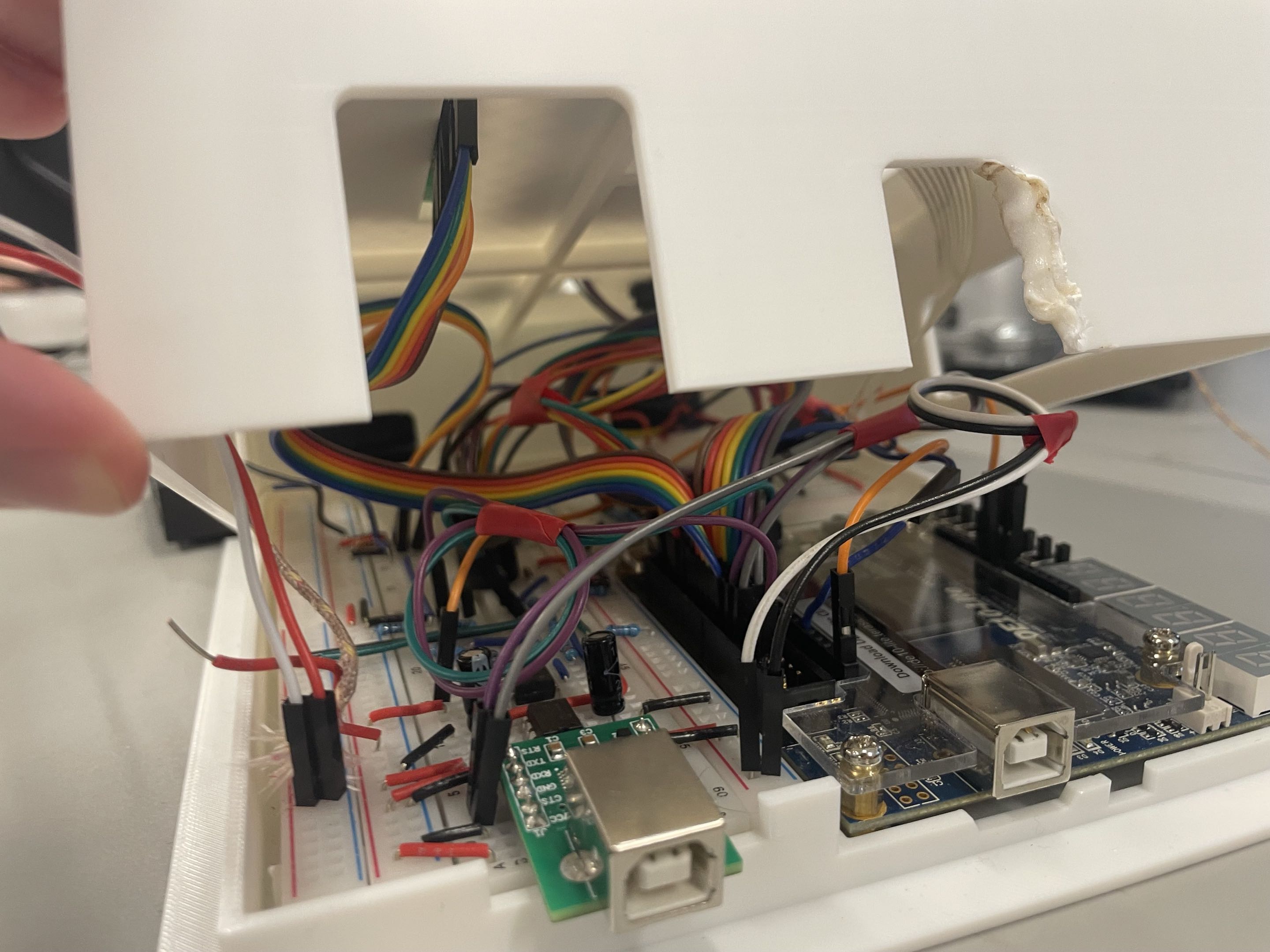
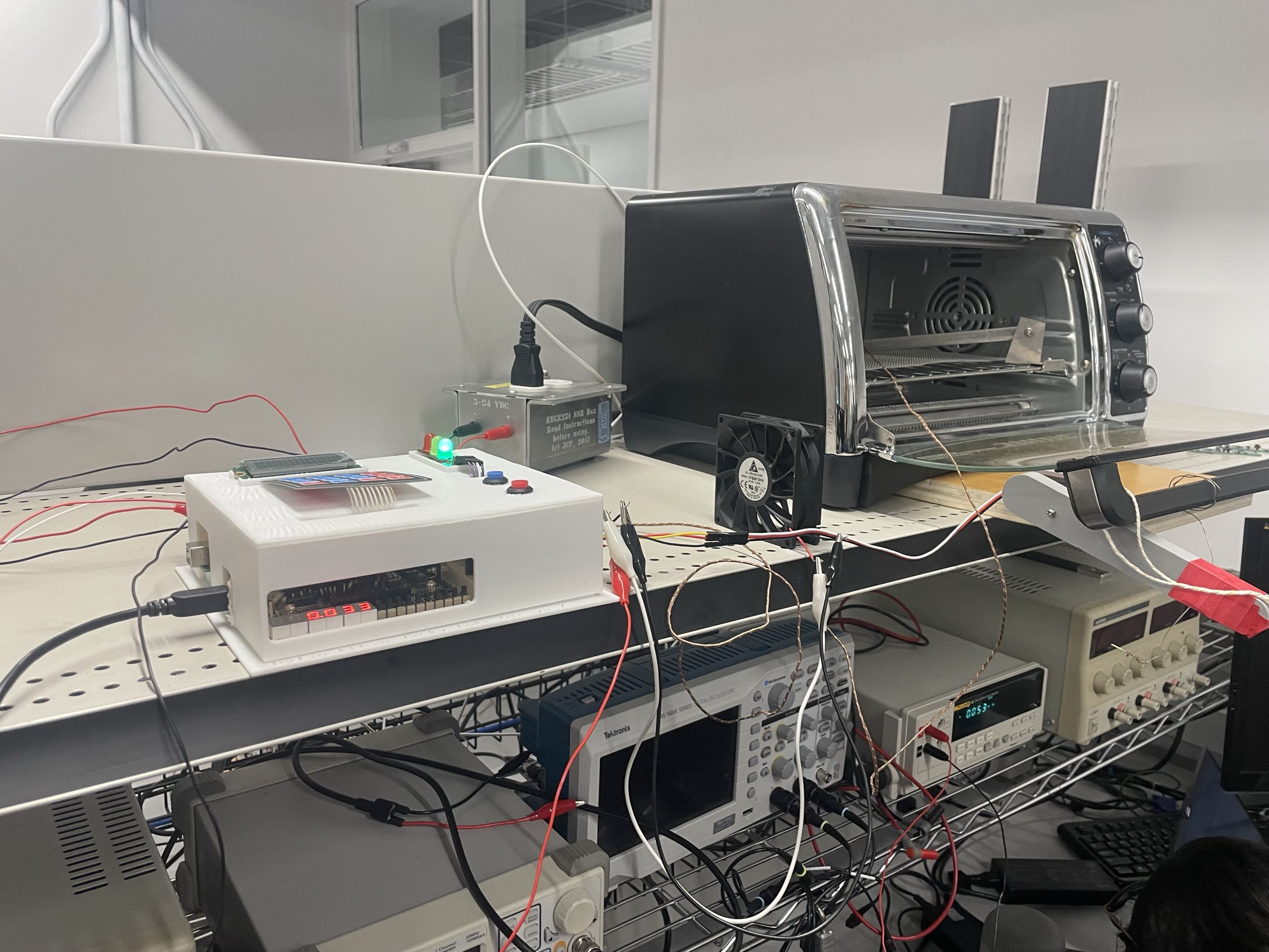
Hardware Architecture: The Peripherals
The hardware architecture relies on a central DE10-Lite controlling various high-voltage and analog peripherals.
1. Temperature Sensing
We utilized a K-type thermocouple wire for thermal measurements. Because the wire produces roughly 43µV/°C, we designed a difference amplifier circuit using an OP07EPZ Op-Amp. We configured it with a gain of ~243 (using 243kΩ and 1kΩ resistors) to scale the 10.32mV max output up to ~2.5V, ensuring it remained cleanly within the microcontroller’s ADC range.
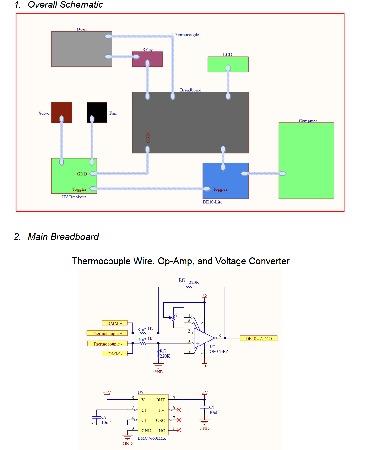
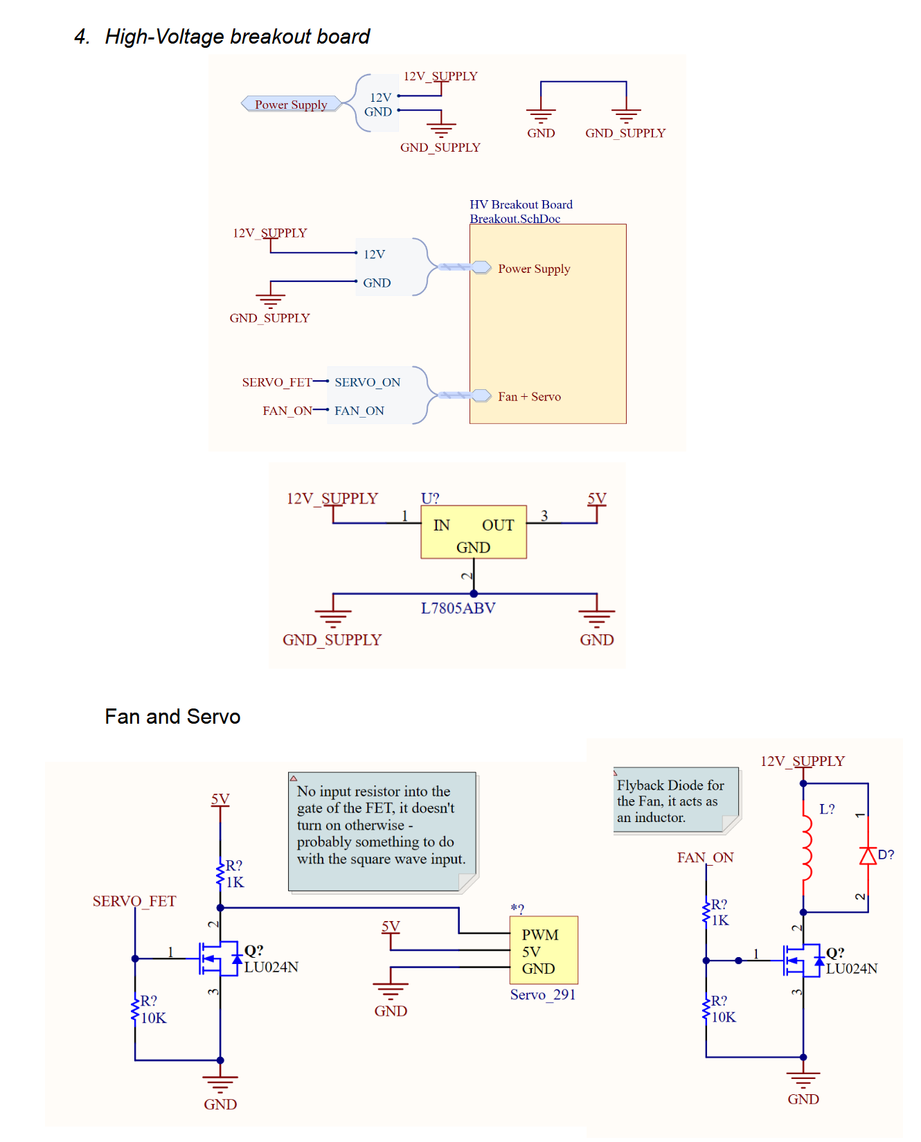
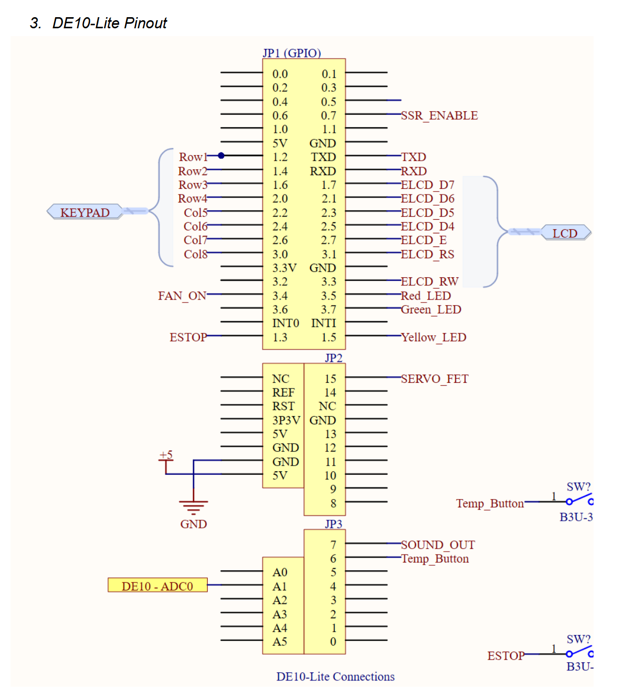
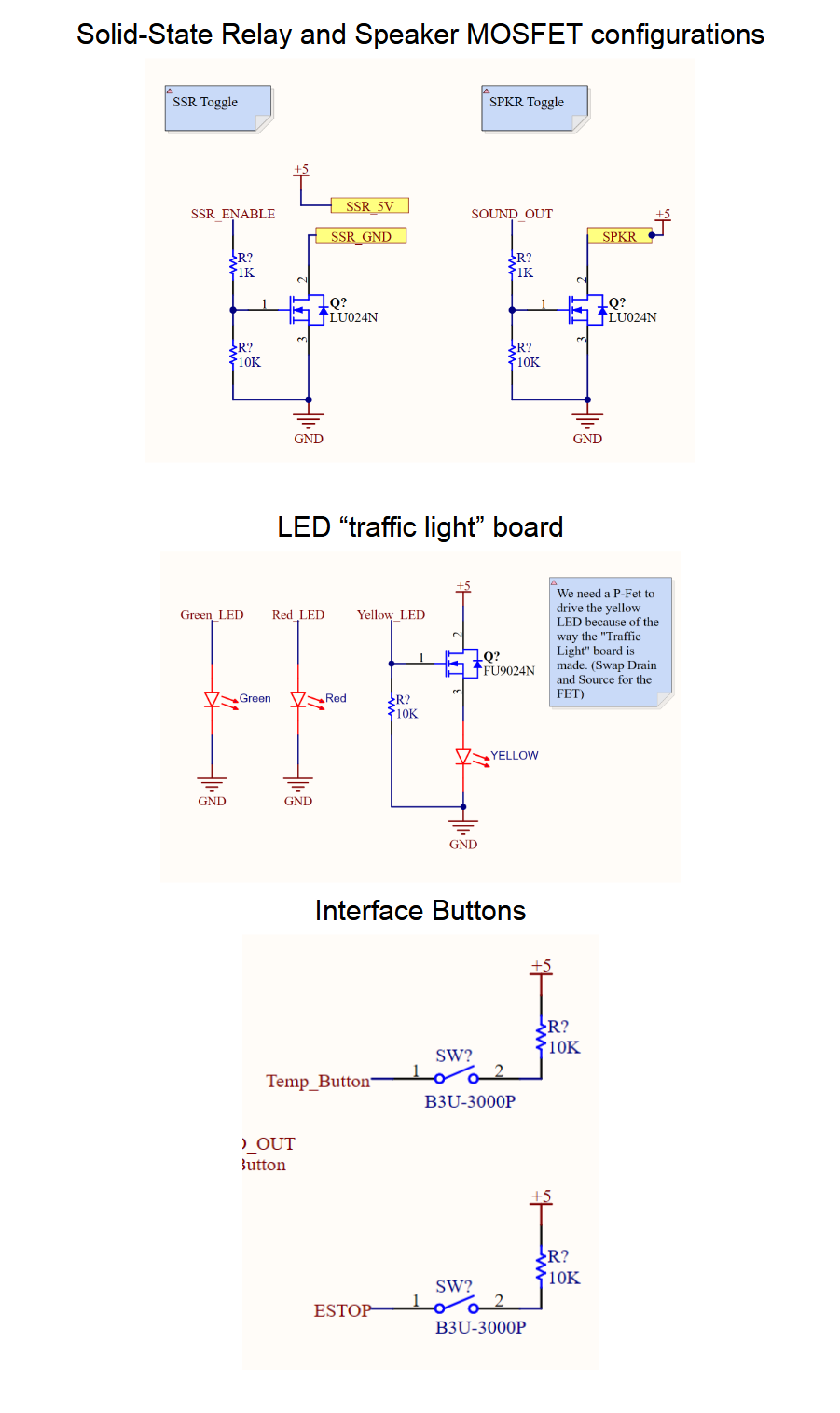
2. Solid-State Power Control
Heating is physically controlled via a Solid-State Relay (SSR). The SSR is driven by an N-channel MOSFET (LU024N) connected directly to a GPIO pin on the DE10-Lite, isolating our delicate logic level circuitry from the 120VAC toaster oven.
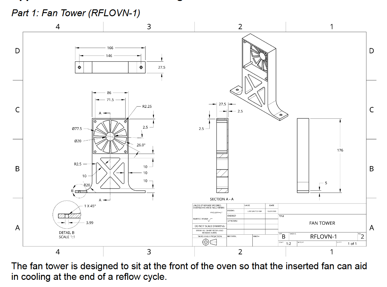
3. Mechanical Cooling System
To drastically improve the cooling decay rate compared to standard passive cooling, we designed a custom mechanical intervention system. This utilized a 3D-printed lever arm attached to a 20Ncm servo to automatically push the oven door open at the end of a cycle, accompanied by a 12V cooling fan mounted on a custom structural tower.
Firmware & System Dynamics 💻
Working in 8051 assembly required careful management of memory, clock cycles, and register banks. The software architecture is split into two primary, decoupled Finite State Machines.
The UI & Frontend FSM
A dedicated front-end FSM handles inputs from a custom 4x4 keypad. It includes debouncing logic and allows users to configure custom temperature profiles, select from three hardcoded presets, toggle between Celsius and Fahrenheit, and safely trigger an emergency stop.
The Core Oven Controller FSM
Driven by a 1ms hardware timer interrupt, this 6-stage FSM manages the physical state of the oven. We utilized an on-off control strategy, deactivating the heater slightly below target temperatures to prevent overshoot caused by the oven’s latent thermal inertia.
; Snippet: Soak Stage Temperature Control Logic
; If temperature > soak_temp - threshold, turn oven off to prevent overshoot
soak_too_hot:
    clr oven_pin           ; Deactivate Solid State Relay
    sjmp check_soak_time   ; Proceed to verify if soak duration has elapsed

check_soak_time:
    Check_Time(soak_time)  ; Macro evaluating 32-bit elapsed time vs target
    mov a, x+0
    jnz FSM1_state2_done   ; If time not met, stay in current state

exit_state2:
    mov sec, #0            ; Reset FSM timer
    mov sec+1, #0
    mov reflow_state, #3   ; Transition to 'Ramp to Peak' state
To manage the timer comparisons, we utilized a custom 32-bit math library capable of processing subtraction, division, and BCD-to-Hex conversions entirely within the 8-bit confines of the 8051 architecture.
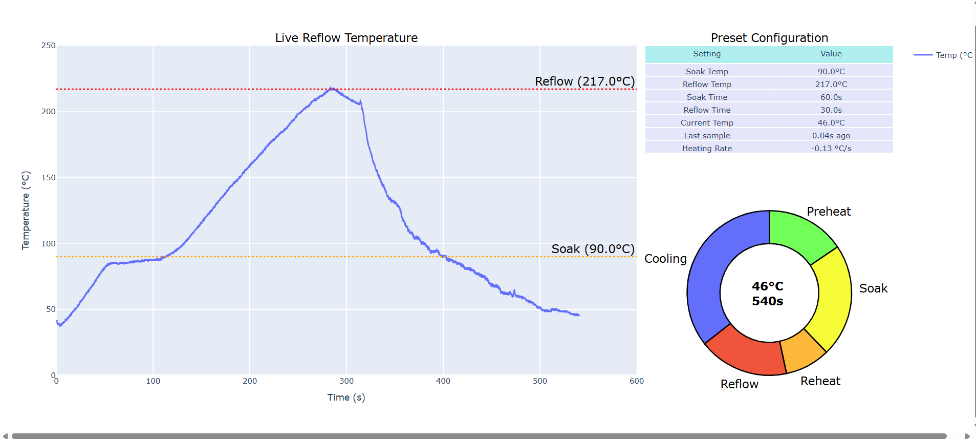
Real-Time Python Dashboard
To validate our system and monitor the reflow process, we developed a Python-based stripchart application. The microcontroller transmits live temperature data, the current FSM stage, and elapsed time via serial over UART. The Python script visualizes this data in real-time, allowing us to actively track the heating rates and ensure the system remained strictly within the +/- 20°C tolerance window required for proper SMD reflow.
Conclusion & Takeaways
This project was a great exercise in embedded systems integration, bridging the gap between hardware, precise analog sensing, and low-level microprocessor control. Successfully translating abstract control concepts into functioning 8051 assembly reinforced the importance of modular code and robust hardware testing methodologies. Our team was rewarded for our efforts with a mark of 98% on this project!