Note: This project was completed with a team of 6 people. While the group work was highly cooperative, my primary contributions dealt with programming the STM32 finite state machine, engineering the EFM8 radio telemetry bridge, integrating the ToF sensor, designing the mixed-signal radar PCB, leading the hardware-software integration across the four boards, and overall project management. I want to give credit to my team members: Jacky Chen, Olesya Kondrateva, Luke Santosham, Yasna Vafi, and Ethan Wong.
Overview
This project was the second project in my Elec 291 course at UBC. The objective of this project was to engineer a robust, autonomous car and remote control system from the ground up. To achieve this, our team developed a distributed architecture spanning four custom-designed PCBs, bare-metal STM32 and EFM8 firmware, and a custom Python control bridge.
The system features:
- Magnetic Line Following utilizing inductor sensors and a tuned proportional-derivative (PD) controller.
- Real-Time Object Avoidance driven by a non-blocking, hardware-timed Time-of-Flight (ToF) I2C driver.
- Custom 32-bit IR & Long-Range RF Protocols capable of transmitting through concrete walls.
- Arcade-Style Control and easy switching between autonomous AI and manual remote control.
System Flow
- Sensors continuously sample track data (via ADC/DMA) and obstacle distance via a Time of Flight sensor.
- STM32 FSM (Finite State Machine) evaluates inputs without blocking the CPU to determine the operational state (
FOLLOW_TRACK,AVOID_OBSTACLE,MANUAL_DRIVE). - PD Controller calculates required motor compensation and directly writes to hardware PWM registers (
CCR). - Python Bridge receives real-time diagnostic data and allows a Python UI or custom Remote Controller to override the AI via nRF24 or IR signals.
- Speed Radar monitors vehicle velocity using a custom mixed-signal Doppler radar board.
Working on this project within a six-person engineering team required careful organization to prevent bottlenecks and hardware-software conflicts. I helped organize the team, breaking down and handing out tasks, and built the main framework for the car firmware. We modularized the bare-metal STM32 codebase to prevent Git merge conflicts, allowing team members to independently tune specific algorithms—like the PD line-follower—without breaking the core state machine. Finally, we employed a phased bring-up strategy, using oscilloscopes to independently validate signal integrity across all four custom PCBs before full system integration, ensuring physical hardware bugs were never mistaken for firmware errors.
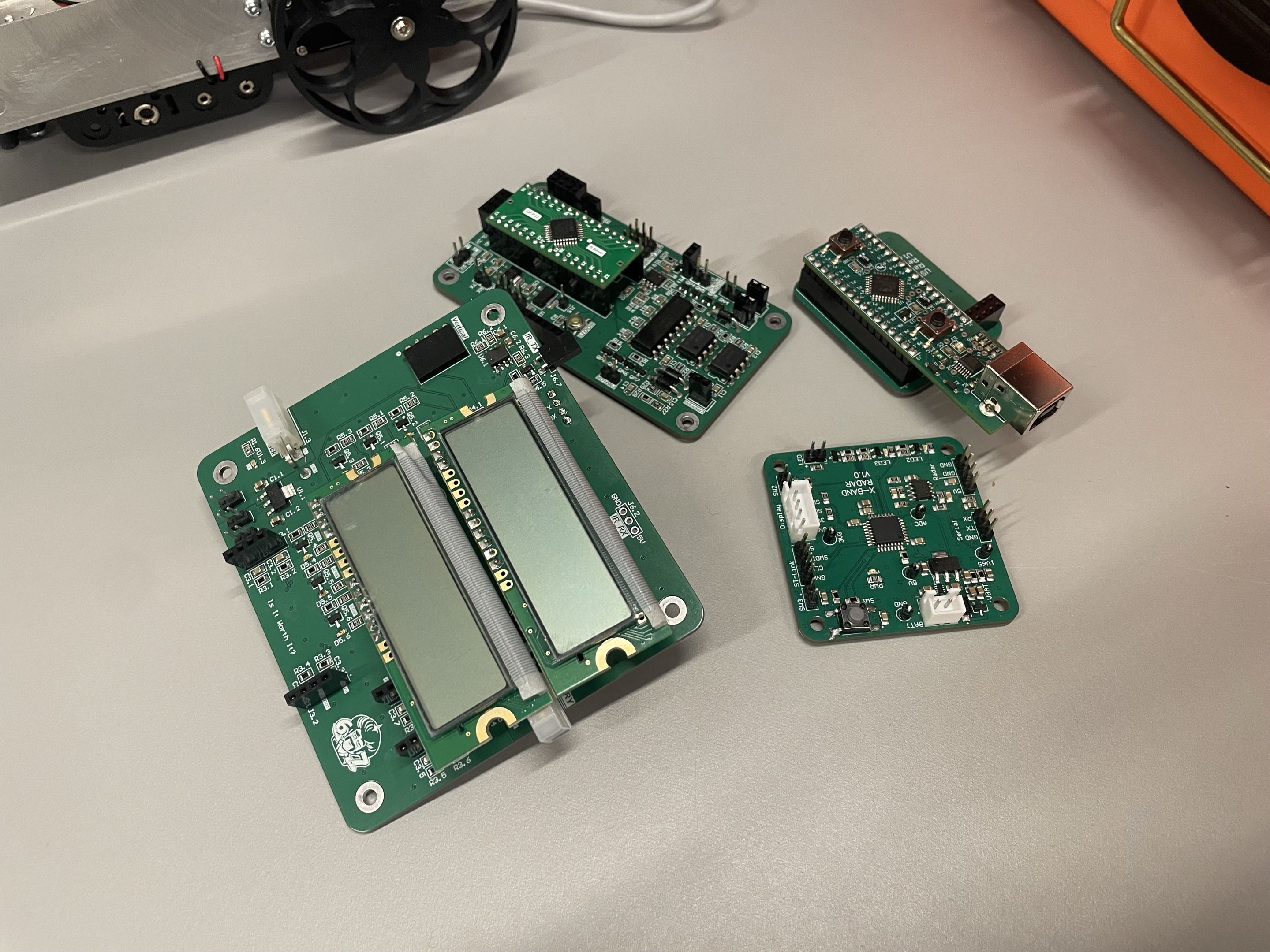
Hardware Architecture: The 4-Board Ecosystem
To isolate high-current motor noise from sensitive logic lines and modularize development, the hardware was split across 4 distinct PCBs designed in Altium Designer.
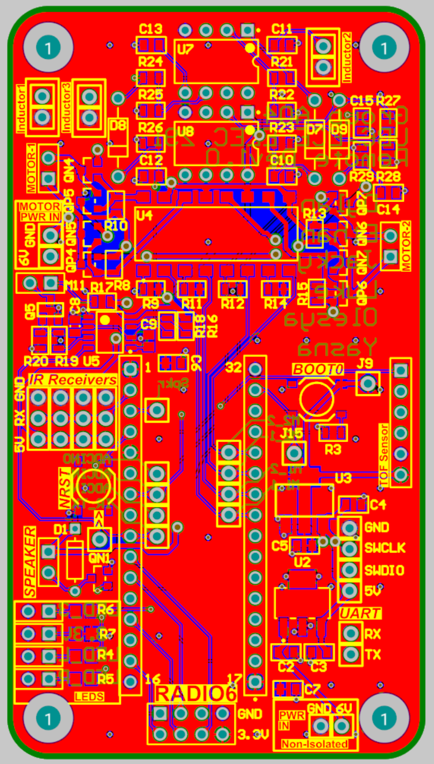
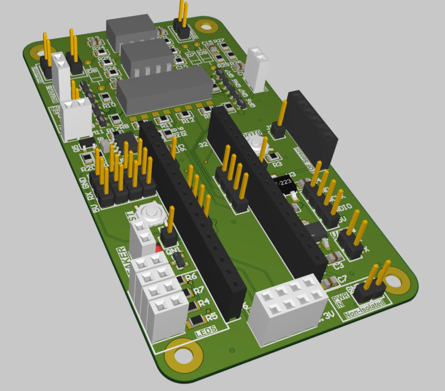
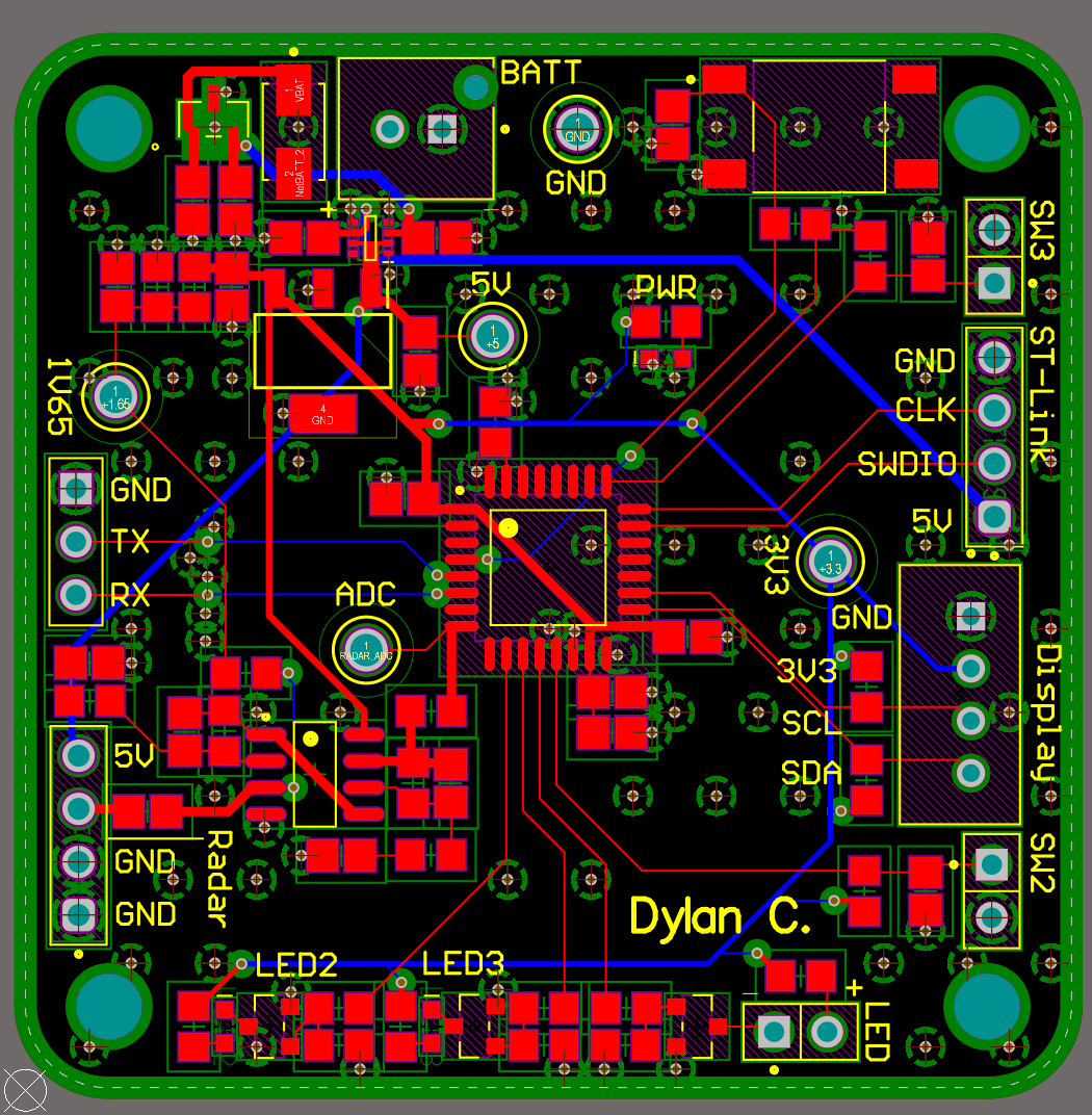
1. The Autonomous Car PCB
A 4-layer mixed-signal board acting as the central brain and power distributor.
- Isolated Power Domains: Utilizes separated PWR/GND planes for the motor H-bridges and the MCU. Power is regulated through two separate LDOs, preventing inductive voltage spikes from browning out the STM32.
- Signal Integrity: A continuous internal ground plane provides a low-impedance return path, tied together with extensive stitching vias.
- Peripherals: Features a dual IR array driven by dedicated MOSFETs for 360º, room-scale communication, an onboard speaker, and an nRF24 radio module.
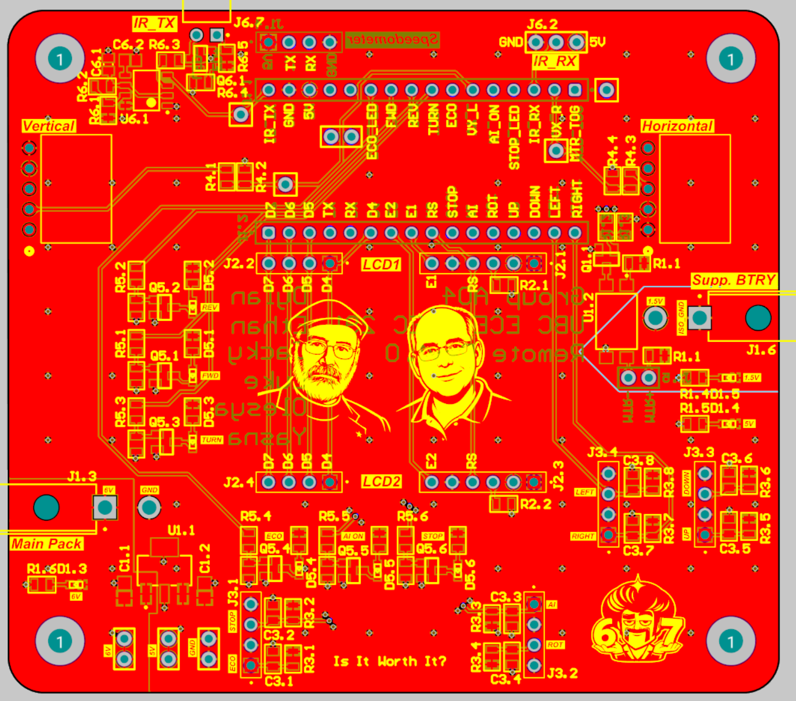
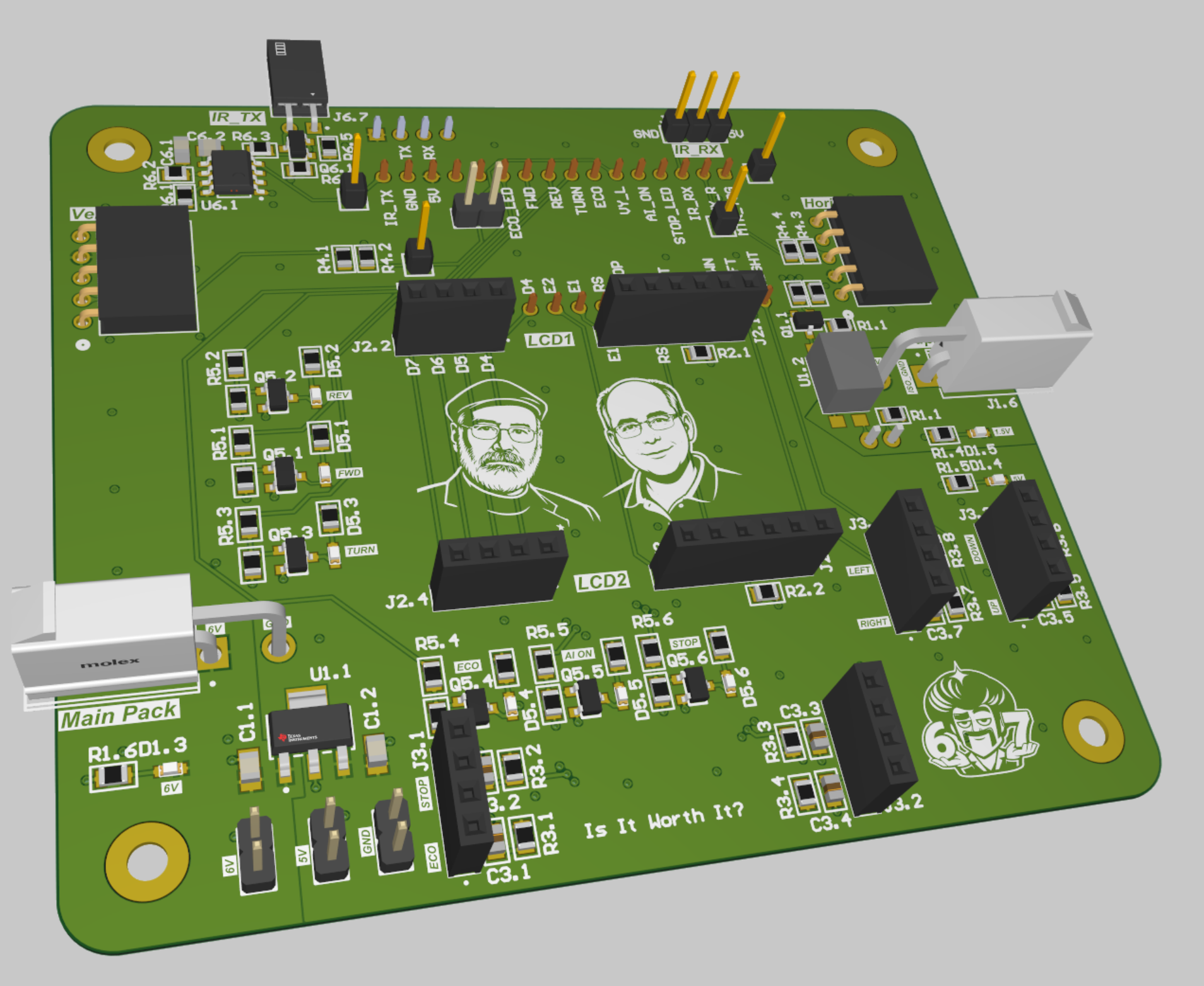
2. The Remote Controller PCB
A custom handheld controller designed for robust human-machine interfacing.
- Mechanical Reliability: Built with robust, crimped Molex connectors to prevent field failures. Housed in a custom 3D-printed enclosure.
- Haptic & Visual Feedback: Incorporates dual LCDs for telemetry and an optocoupler-isolated haptic vibration motor to physically alert the driver of mode changes or obstacles.
- UI Controls: Features dual joysticks, an Eco-mode toggle, a rotation override button, and path-preset selectors.
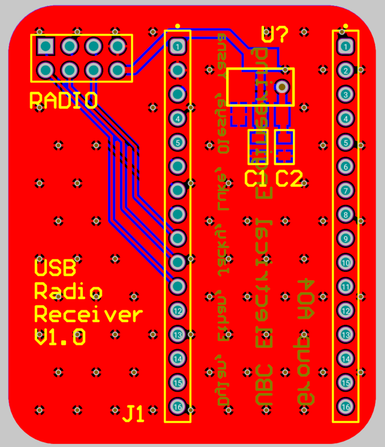
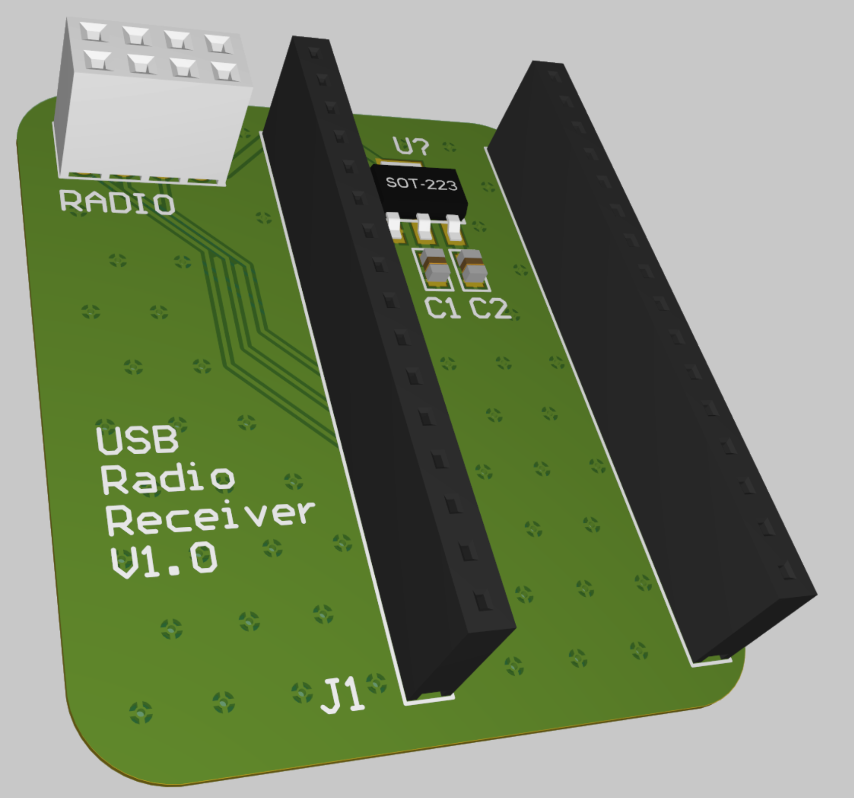
3. The Radio Telemetry Bridge
A dedicated USB-to-RF PCB connecting the physical robot to a laptop.
- Design: Built around an EFM8 microcontroller and an nRF24 module, utilizing proper RF grounding practices to achieve >25m transmission range through concrete walls.
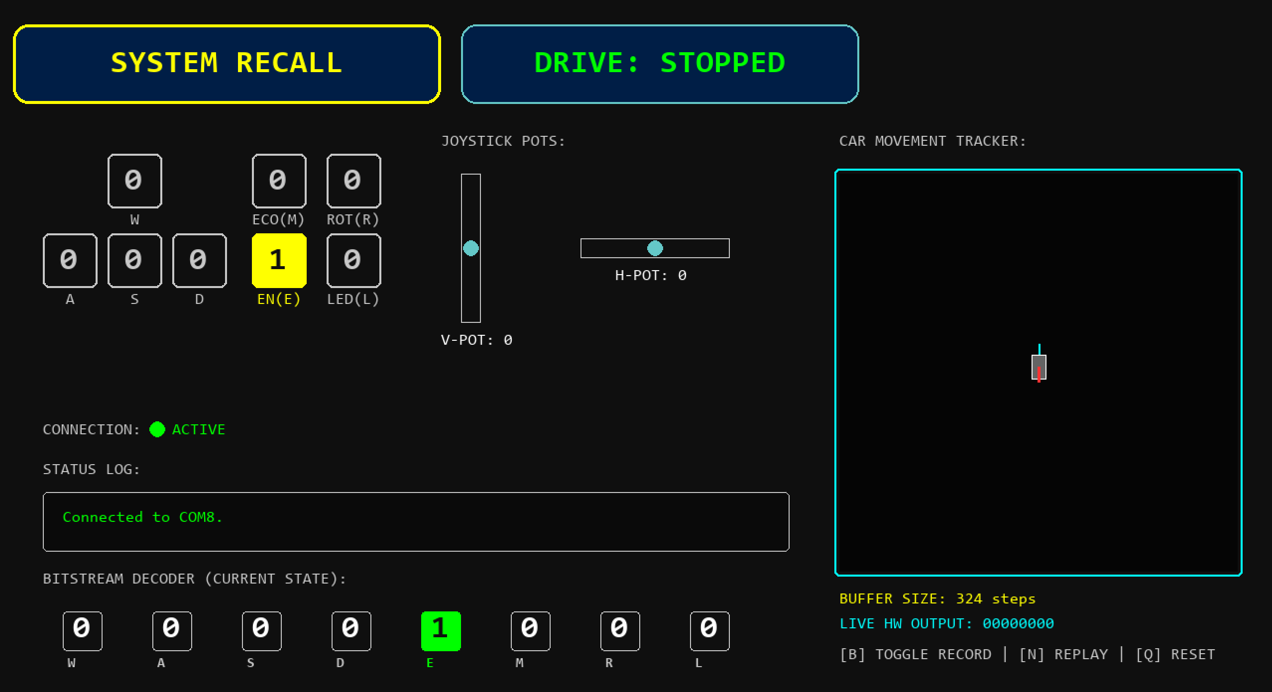
- Function: Acts as a transparent serial bridge, allowing our custom Python UI to send WASD commands, draw out preset execution paths, and log real-time vehicle states.
4. The Doppler Speed Radar PCB
Integrated as a diagnostic and tracking sub-system, this board handles the analog signal processing of a 10.5 GHz radar wave to calculate velocity via an onboard FFT pipeline. (Read the deep dive on this specific board here).
—
Firmware & System Dynamics
The firmware was written in bare-metal C. Avoiding heavy abstraction layers like RTOS or blocking HAL_Delay() functions was critical to maintaining high-frequency control loops.
Non-Blocking Sensor Fusion
A major focus for me was preventing the I2C Time-of-Flight sensor from paralyzing the CPU. The VL53L0X requires ~33ms to physically bounce photons off a wall. Instead of blocking the CPU in a while() loop, the I2C driver relies on a specifically scaled hardware timer (TIM6). The timer prescaler maps 1 tick to exactly 1 millisecond, querying the I2C bus only when the hardware is guaranteed to be ready, leaving the CPU 100% free to calculate motor kinematics.
void TurnMTR(int8_t horz, int8_t vert, uint8_t eco_flag) {
    // Eco mode multiplier
    uint8_t eco_off = eco_flag ? 1 : 2;

    // Calculate signed power vectors for Arcade Drive
    int32_t left_power = ((int32_t)vert + (int32_t)horz) * 4 * eco_off;
    int32_t right_power = ((int32_t)vert - (int32_t)horz) * 4 * eco_off;

    // Cap the maximum values to prevent timer overflow
    if(left_power > 999) left_power = 999;
    if(left_power < -999) left_power = -999;
    if(right_power > 999) right_power = 999;
    if(right_power < -999) right_power = -999;

    // Apply Left Motor Direction (Write directly to TIM2 Hardware Registers)
    if (left_power > 0) {
        TIM2->CCR1 = left_power;        // Forward
        TIM2->CCR2 = 0;
    } else if (left_power < 0) {
        TIM2->CCR1 = 0;
        TIM2->CCR2 = abs(left_power);   // Reverse
    } else {
        TIM2->CCR1 = 0;
        TIM2->CCR2 = 0;                 // Stop
    }

    // (Right motor applies identical logic to TIM22)
}
By writing the calculated vectors directly to the CCR (Capture/Compare) registers of the hardware timers, we bypassed software latency entirely, resulting in incredibly smooth, instantaneous maneuvers without any “jerking” or FSM lag.
Wireless Protocols & Hardware Hacks
32-Bit IR Protocol
To ensure our Remote Controller only communicated with our specific vehicle in a crowded lab environment, we developed a professional 32-bit IR communication profile.
- It utilizes a specific device address header.
- The payload is half-inverted (sending the data, followed immediately by the bitwise NOT of the data). The receiver compares the two halves to guarantee mathematical correctness before executing a command, completely rejecting ambient light noise and interference.
The EFM8 Silicon Limitation
During the bring-up of the Radio Receiver PCB, we encountered a hard physical limitation: The EFM8 microcontroller’s Priority Crossbar Decoder could not route hardware SPI lines to Port 3, where the nRF24 radio was physically wired. Instead of hacking up the custom PCB with jumper wires, we wrote a custom bit-banged SPI driver in C. By manually toggling the GPIO pins in sequence to mimic shift-register behavior, we successfully established a stable 115200 baud pipeline to the laptop without altering the physical copper.
Future Revisions
While the current architecture successfully navigates complex tracks and maintains a highly reliable RF/IR link, future revisions could explore:
- Sensor Fusion: Combining the ToF distance data with the Doppler Radar velocity data to create an intelligent braking algorithm (calculating the exact time-to-impact).
- Closed-Loop Motor Encoders: Upgrading from standard DC motors to motors with quadrature encoders to allow for precise dead-reckoning and exact 90-degree rotational commands, rather than relying strictly on timer-based turning.